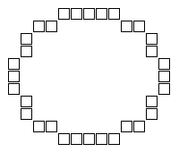
Figure 1: An outline of an approximate ellipse.
Basser Department of Computer Science
University of Sydney,
New South Wales, 2006, Australia
October 4, 2001
These shapes are only approximated by the discrete pixels available on the display device so the result often looks blocky, especially when magnified, as in Figure 1. Here, each pixel changed by an ellipse-drawing algorithm is represented by the outline of a square.

Throughout this paper, the diagrams in this paper show magnified pixels with small gaps between pixels, or between rectangular blocks of pixels. These gaps would not appear in the actual shape drawn by each of the algorithms described. They have been introduced to make the explanations of the algorithms clearer.
For the moment, we will only be considering algorithms which draw axis-aligned ellipses, that is, ellipses which are symmetrical about horizontal and vertical axes drawn through the centre of the ellipse. We will develop an algorithm which draws shapes having the same boundary points as ellipses drawn by an algorithm described by McIlroy [1992]. McIlroy's algorithm draws Freeman approximations [Freeman 1974] of axis-aligned ellipses, and has been used in the Plan 9 operating system's windowing library [Pike 1991].
McIlroy's algorithm has advantages over other ellipse algorithms. As McIlroy notes, some published algorithms do not produce good approximations to an ellipse. They may not have been correctly mathematically derived. Some were generalised from already specialised algorithms used to draw circles. Some produce 'tails' of pixels which are artifacts occurring in special, rare cases. McIlroy's ellipse algorithm carefully avoids many of these problems. Because the filled ellipse algorithm introduced here shares the same boundary points as McIlroy's, our algorithm inherits the good features of his algorithm. We do not need to base our algorithm upon McIlroy's necessarily; another method of finding the boundary points may work equally well. We adapt his algorithm from one which draws the outline of an ellipse, to one which fills the ellipse.
The filled ellipse algorithm developed in this paper uses filled rectangles as its basis. We show that the number of rectangles needed by this algorithm is minimal, and equivalent to a family of similar algorithms. Experimental evidence shows this algorithm is better than naive scan-line algorithms, producing only 59% as many drawing requests as a comparable scan-line algorithm, for near circular shapes, with lesser improvements for more eccentric shapes.
The main reason to use rectangles is portability. A filled rectangle operation exists in most, if not all, graphics systems in existence today. Drawing an ellipse using filled rectangles should modify the same pixels on many platforms.
Instead of using rectangles, we could use a graphics system's filled ellipse routine, but this would not guarantee the pixels are in the same places on every platform. In fact, we have observed one system (Microsoft Windows 3.11 for Workgroups) where ellipses drawn using a native filled ellipse operation are egg-shaped (non-symmetrical).
A filled polygon operation might be another possible way to draw the same pixels on many platforms. Unfortunately, different graphics systems may use different line algorithms to define how diagonal lines in a polygon's boundary are connected. This could give rise to slight variations in which pixels are drawn. For this reason we prefer to concentrate on rectangles, because we can exactly specify which pixels are drawn.
Algorithms which ensure each pixel is changed only once have some important properties, one of which is they behave well when using an exclusive-or drawing mode. Exclusive-or drawing mode on a video screen draws pixels such that drawing the same pixel twice restores the original colour. This mode is often used in 'stretching' or 'rubber-banding' a shape using the mouse. If using an exclusive-or drawing mode, an algorithm which is not guaranteed to change each pixel only once may cause the final shape to contain 'holes' where any pixels are drawn an even number of times.
Even if this were not the case, an algorithm which draws over some areas more than once may be noticeably slower because of the inefficiency involved. With fast modern video display hardware this might not be noticed, but it certainly would be noticed on an ink printer or plotter if ink was repeatedly applied to certain locations inside the shape but not others.
For these reasons, algorithms which change pixels only once are useful and important, and our algorithm uses non-overlapping rectangle to satisfy this requirement.
It is desirable to make any algorithm which uses filled rectangles as its basic operation as efficient as possible.
We start with McIlroy's algorithm, which draws the outline of an ellipse as in Figure 1. We will modify this algorithm to merge adjacent points on the same horizontal line into scan lines (rectangles one pixel tall). We will then modify this scan line algorithm to merge adjacent scan lines with the same width into fewer, taller, filled rectangles.
The algorithm efficiently draws the outline exploiting symmetry to avoid duplicate calculation. Once a point is calculated in one quadrant of the shape, symmetry about horizontal and vertical axes reveals where the reflected points should be drawn.
We present the algorithm as C source code. It is usually unwise to represent an algorithm as code, because of implicit arithmetical limitations and the danger of optimisations obscuring or distorting algorithmic features. In this case, we strive to show that the derivation of our new algorithm is invariant with respect to the arithmetic of McIlroy's algorithm. Giving a concrete implementation was felt to be the best way to illustrate that point.
	extern void point(int x, int y);

	#define incx() x++, dxt += d2xt, t += dxt
	#define incy() y--, dyt += d2yt, t += dyt

	void draw_ellipse_1(int xc, int yc, int a, int b)
	{			/* e(x,y) = b^2*x^2 + a^2*y^2 - a^2*b^2 */
		int x = 0, y = b;
		long a2 = (long)a*a, b2 = (long)b*b;
		long crit1 = -(a2/4 + a%2 + b2);
		long crit2 = -(b2/4 + b%2 + a2);
		long crit3 = -(b2/4 + b%2);
		long t = -a2*y; /* e(x+1/2,y-1/2) - (a^2+b^2)/4 */
		long dxt = 2*b2*x, dyt = -2*a2*y;
		long d2xt = 2*b2, d2yt = 2*a2;

		while (y>=0 && x<=a) {
			point(xc+x, yc+y);
			if (x!=0 || y!=0)
				point(xc-x, yc-y);
			if (x!=0 && y!=0) {
				point(xc+x, yc-y);
				point(xc-x, yc+y);
			}
			if (t + b2*x <= crit1 ||   /* e(x+1,y-1/2) <= 0 */
			    t + a2*y <= crit3)     /* e(x+1/2,y) <= 0 */
				incx();
			else if (t - a2*y > crit2) /* e(x+1/2,y-1) > 0 */
				incy();
			else {
				incx();
				incy();
			}
		}
	}
The central point of the ellipse is (xc,yc), with the semi-major axis being a pixels in length, and the semi-minor axis b pixels in length. The point routine draws a single pixel. The first two if tests within the loop avoid drawing the same point more than once. The if ... else if ... else part of the loop increments integer variables to step around one quadrant of the ellipse a pixel at a time. The first of these tests handles the case that the x value needs to be stepped outwards, while y remains constant (a horizontal motion). The second test handles a decrease in y as x stays constant (a vertical motion). The final test handles the simultaneous increase in x and decrease in y (a diagonal motion).
The code has an arithmetical limitation. If we assume 32-bit long integers, overflow does not occur for values of a and b less than 896. The transformations we will perform on the code do not change this limitation one way or another.
Figure 2 illustrates how this algorithm draws pixels from a vertical middle line outwards. The numbers in each pixel square show the order in which they are drawn. We assume the standard convention in graphics programming, that x increases to the right, and y increases down the page.

We begin with McIlroy's algorithm, which draws each pixel of the outline as it calculates the co-ordinates. We will modify this algorithm so it remembers a row of pixels, which has starting x and y co-ordinates, and a width in pixels.
Stepping x outwards increases the width of the row by two pixels (through symmetry). Stepping y causes the row to be drawn. We can exploit symmetry about a horizontal axis to draw two rows at once, one above this middle line, and one below. This transformation does not modify the arithmetic underlying McIlroy's algorithm, but simply caches drawing requests to draw rows of pixels instead of individual points. We present this algorithm as C code.
	extern void row(int x, int y, unsigned int width);

	#define incx() x++, dxt += d2xt, t += dxt
	#define incy() y--, dyt += d2yt, t += dyt

	void fill_ellipse_1(int xc, int yc, int a, int b)
	{			/* e(x,y) = b^2*x^2 + a^2*y^2 - a^2*b^2 */
		int x = 0, y = b;
		unsigned int width = 1;
		long a2 = (long)a*a, b2 = (long)b*b;
		long crit1 = -(a2/4 + a%2 + b2);
		long crit2 = -(b2/4 + b%2 + a2);
		long crit3 = -(b2/4 + b%2);
		long t = -a2*y; /* e(x+1/2,y-1/2) - (a^2+b^2)/4 */
		long dxt = 2*b2*x, dyt = -2*a2*y;
		long d2xt = 2*b2, d2yt = 2*a2;

		while (y>=0 && x<=a) {
			if (t + b2*x <= crit1 ||     /* e(x+1,y-1/2) <= 0 */
			    t + a2*y <= crit3) {     /* e(x+1/2,y) <= 0 */
				incx();
				width += 2;
			}
			else if (t - a2*y > crit2) { /* e(x+1/2,y-1) > 0 */
				row(xc-x, yc-y, width);
				if (y!=0)
					row(xc-x, yc+y, width);
				incy();
			}
			else {
				row(xc-x, yc-y, width);
				if (y!=0)
					row(xc-x, yc+y, width);
				incx();
				incy();
				width += 2;
			}
		}
		if (b == 0)
			row(xc-a, yc, 2*a+1);
	}
The main change from the earlier algorithm code, is that the drawing occurs inside the if ... else if ... else statement. The row routine draws a horizontal row of pixels. Symmetry about a horizontal axis is used to draw two rows sequentially. The test for y is not zero avoids drawing the same row of pixels twice at the middle of the ellipse.
The width variable begins at a value of one, because McIlroy's algorithm draws points which are one pixel in width. It begins drawing at the vertical axis of symmetry (where x is zero), and draws outwards until x is equal to a. The width of the shape will be 2a+1 pixels. For similar reasons the height of the shape will be 2b+1 pixels. Initialising the width to one accounts for the single row at the middle of the ellipse, running through the horizontal axis.
The final test outside the loop handles the case that there are no vertical steps in the shape, and hence no drawing will have yet been performed, since drawing a row only occurs within the loop as a result of a change in y. In this situation, b must be zero, so we draw a single row of pixels spanning the width of the shape, which is 2a+1. This test could even have been performed before the loop, for efficiency. Note we should not use the x or width values after the loop, because x will be equal to a+1 to exit the loop, and hence width will be 2a+3, which is wider than the ellipse. This special case only occurs when b equals zero, because of the delayed drawing technique.
The fact that the width variable is an unsigned quantity is worth noting. An unsigned integer can hold twice the range of values that a signed integer can. As x approaches a, the width will approach 2a+1. If a was more than half the maximum integer value, using an unsigned integer for the width avoids overflow. For 16-bit integers, this would occur when x was 16384; in that case width would be 32769. Of course, the algorithm itself overflows at much lower values if long integers are 32 bits in size (as noted before) so this is perhaps a minor consideration. In that case, width could safely be defined as a signed integer.
Filled Ellipse Algorithm 1 draws shapes such as that shown in Figure 3.

The numbers in each rectangular scan line show the order in which they are drawn.
Starting with Filled Ellipse Algorithm 1, we introduce a new variable to keep track of the height of the rectangle to be drawn. Initially this value starts at one pixel. When y changes we do not immediately draw the row. Instead, we increase the height of the stored rectangle to incorporate both the current row and the previous row. If x changes we must check if the height of the row is greater than one. If it is, this means a width change is occuring and we already have a stored rectangle, so we must draw the stored rectangle before proceeding. If the rectangle is only one pixel tall, we can just increase its width without drawing it.
This is essentially a way of caching and accumulating adjacent scan lines into larger rectangles, for subsequent rendering. We can still exploit symmetry to draw the top and bottom half of the shape, except we must be careful to merge the rectangles when we reach the middle, lest an overlap occur.
	extern void fill_rect(int x, int y,
			      unsigned int width, unsigned int height);

	#define incx() x++, dxt += d2xt, t += dxt
	#define incy() y--, dyt += d2yt, t += dyt

	void fill_ellipse_2(int xc, int yc, int a, int b)
	{			/* e(x,y) = b^2*x^2 + a^2*y^2 - a^2*b^2 */
		int x = 0, y = b;
		int rx = x, ry = y;
		unsigned int width = 1;
		unsigned int height = 1;
		long a2 = (long)a*a, b2 = (long)b*b;
		long crit1 = -(a2/4 + a%2 + b2);
		long crit2 = -(b2/4 + b%2 + a2);
		long crit3 = -(b2/4 + b%2);
		long t = -a2*y; /* e(x+1/2,y-1/2) - (a^2+b^2)/4 */
		long dxt = 2*b2*x, dyt = -2*a2*y;
		long d2xt = 2*b2, d2yt = 2*a2;

		if (b == 0) {
			fill_rect(xc-a, yc, 2*a+1, 1);
			return;
		}

		while (y>=0 && x<=a) {
			if (t + b2*x <= crit1 ||     /* e(x+1,y-1/2) <= 0 */
			    t + a2*y <= crit3) {     /* e(x+1/2,y) <= 0 */
				if (height == 1)
					; /* draw nothing */
				else if (ry*2+1 > (height-1)*2) {
					fill_rect(xc-rx, yc-ry, width, height-1);
					fill_rect(xc-rx, yc+ry+1, width, 1-height);
					ry -= height-1;
					height = 1;
				}
				else {
					fill_rect(xc-rx, yc-ry, width, ry*2+1);
					ry -= ry;
					height = 1;
				}
				incx();
				rx++;
				width += 2;
			}
			else if (t - a2*y > crit2) { /* e(x+1/2,y-1) > 0 */
				incy();
				height++;
			}
			else {
				if (ry*2+1 > height*2) {
					fill_rect(xc-rx, yc-ry, width, height);
					fill_rect(xc-rx, yc+ry+1, width, -height);
				}
				else {
					fill_rect(xc-rx, yc-ry, width, ry*2+1);
				}
				incx();
				incy();
				rx++;
				width += 2;
				ry -= height;
				height = 1;
			}
		}

		if (ry > height) {
			fill_rect(xc-rx, yc-ry, width, height);
			fill_rect(xc-rx, yc+ry+1, width, -height);
		}
		else {
			fill_rect(xc-rx, yc-ry, width, ry*2+1);
		}
	}
Three new variables have been introduced: rx remembers the stored rectangle's x value, ry the stored y value, and height remembers its height in pixels. We use a fill_rect routine to draw a filled rectangle of the given width and height. If either the width or height is zero, nothing is drawn. If the height is negative, the rectangle will be drawn above the y line rather than hanging below it.
The test if b is zero has been moved above the loop, as suggested in discussions on the previous algorithm. Little arithmetic needs to be performed in that case, so it is simpler to handle it specially.
The first if test within the loop handles the case that x is being increased, a horizontal step. As before, the width is increased by two pixels whenever x increases. Before that occurs, we must determine if the stored rectangle needs to be drawn. If the height of that rectangle is one pixel, this means we haven't seen any changes in y for this row, so we can just increase the width and draw nothing. This is the equivalent of accumulating two pixels onto the end of a single row. If the height is greater than one, we've already seen a change in y, and now we have to handle a change in x. Thus we must emit the stored rectangle, excluding the current row, and then reset the rectangle to handle the current row. The two else parts draw the rectangle on either side of a horizontal axis line, if the rectangles would be distinct, or if they would overlap, respectively.
In the second if test within the loop, y is being changed, but x remains the same. This corresponds to increasing the height of the stored rectangle by one pixel. Since x is not changing there is no need to draw anything yet.
The final else part within the loop handles a diagonal motion, where both x and y change. In that case, we know the stored rectangle must be drawn before continuing. First we check there is no overlap between rectangles above and below the middle line and in that case draw two rectangles. If they would overlap, we draw one rectangle crossing the horizontal axis line. ry is the distance from the horizontal axis that a stored rectangle will be drawn. As mentioned earlier, the height of the entire ellipse will be 2b+1, with the +1 term arising due to symmetry about a central horizontal row of pixels. Bearing in mind the existence of this central row of pixels, we can see that if 2*ry+1 is greater than the sum of the heights of the stored rectangles above and below the horizontal axis, the two rectangles will be distinct.
After the loop, there is another if ... else statement designed to draw any remaining stored rectangles which have not yet been drawn. Again, we check to see if the rectangles have joined at the middle, in which case we need only draw a single rectangle.
Filled Ellipse Algorithm 2 draws filled elliptical shapes using the pattern shown in Figure 4.

Because we have modified an existing algorithm which is known to produce good approximations to an ellipse, and since we have been careful not to distort the shape or change the arithmetic, we can be sure that the new algorithm fills an approximate ellipse sharing the same borders as the earlier algorithms. The main improvement Filled Ellipse Algorithm 2 makes is to reduce the number of rectangles required to draw the shape.
There are ways to optimise the algorithm further, by removing redundant conditionals and splitting the loop into four loops, each designed to draw different parts of the shape. McIlroy notes several of these improvements in his paper. For simplicity in presenting our algorithm, we avoid such optimisations here.
Definition 1: The term approximate ellipse refers to a filled shape with no disconnected areas or holes, which approximates an ellipse on a pixel grid.
Definition 2: A shape is vertically symmetrical if a hypothetical vertical axis can be drawn such that all pixels within the boundary of the shape would map to other pixels within the boundary of the shape when reflected about that axis.
Definition 3: A shape is horizontally symmetrical if a hypothetical horizontal axis can be drawn such that all pixels within the boundary of the shape would map to other pixels within the boundary of the shape when reflected about that axis.
Definition 4: A shape is axis-aligned if it is vertically and horizontally symmetrical.
The ellipses given as examples so far are axis-aligned approximate ellipses. Axis-aligned implies the shape has four quadrants, each of which is a mirror image of the two adjacent quadrants.
Ellipses can be drawn axis-aligned by an algorithm which calculates the corner points of one quadrant of the shape, and reflects the co-ordinates produced to generate corner points having the same x or y co-ordinates in the other three quadrants. This is the technique used in the three algorithms discussed so far.
Definition 5: An outward corner of a vertically and horizontally symmetrical connected shape is defined as a point on the boundary of the shape where the boundary lines touching it form an angle of 90 degrees, seen from the inside of the shape.
Definiton 6: An inward corner, by contrast, points towards the inside of the shape, and is formed by the meeting of boundary lines at an angle of 270 degrees, when seen from the inside of the shape.
In Figure 5, these two concepts are illustrated.

Definition 7: A crossing occurs when a rectangle contains pixels which are contained by another rectangle.
In the case of the ellipse from Figure 4, there are sixteen outward corners. Theorem 1 states that the minimum number of non-overlapping rectangles we can use is half N minus one, which is seven. This is the number produced by the pattern in Figure 4.
Where does the formula N/2 - 1 come from? It arises from the observation that we can fill an ellipse by first drawing a large rectangle that crosses the entire shape, touching four outward corners. To avoid crossing that rectangle, we must now draw other rectangles around it. Each of those other rectangles can touch at most two outward corners. Thus, of the sixteen outward corners seen in Figure 4, four can be generated from one rectangle, and the remaining twelve corners can only be generated by a minimum of six rectangles (which is (N - 4) / 2, or N/2 - 2.) When we add the first rectangle we generated, this amounts to N/2 - 1 non-overlapping rectangles.
A more formal proof follows.
Proof of Theorem 1
Crossings must be avoided, to fulfil the constraint that the rectangles produced are non-overlapping. If we draw a rectangle which touches four outward corners, that rectangle must contain the centre point of the ellipse. Clearly, to avoid crossings, no two rectangles can both contain the centre point.
Observe that we can therefore draw at most one rectangle which touches four outward corners of the ellipse.
Observe also that we can draw no rectangles which touch exactly three outward corners. A rectangle which touches three corners, must logically touch four corners, because of the symmetrical nature of the shape we are discussing.
We may draw rectangles which touch precisely two outward corners, if the other two corners of the rectangle are not outward corners. Figure 4 shows many rectangles which touch exactly two outward corners.
We may also draw rectangles which touch precisely one outward corner, but since we are attempting to minimise the number of rectangles used to fill the shape, this is not to our advantage. For a given shape with a fixed number of corners, we will produce the smallest number of rectangles by maximising the number of corners each rectangle touches. Using rectangles which touch only one corner point will only introduce more rectangles into the shape. This point is illustrated in Figure 6.

More formally, the number of non-overlapping rectangles which is used to fill an axis-aligned ellipse can be written as:
4A + 2B + C = Nwhere A is the number of rectangles which touch four outward corners, B is the number which touch two outward corners, and C is the number which touch only one outward corner. N is the total number of outward corners in a given ellipse.
To reduce the total number of rectangles used, we wish to minimise the expression
A + B + CWe know that A can only be zero or one, since having more than one rectangle touching four corner points produces a crossing. It is clear that in minimising this expression, we prefer B to be maximal and C to be minimal, in order to touch more corners with fewer rectangles. So the best we can do is if A is one, and C is zero, and B is therefore
	4 + 2B = N
	B = (N - 4) / 2
and so the total number of rectangles is
	A + B = 1 + (N - 4) / 2
	      = N/2 - 1
Thus, the minimum number of non-overlapping rectangles can be obtained by using one rectangle which touches four outward corners, and the remaining rectangles should touch two outward corners each.
Filled Ellipse Algorithm 2, which produces the pattern of rectangles seen in Figure 4, clearly always generates this minimum number of rectangles, because it uses precisely the technique used to prove Theorem 1, namely one large rectangle which crosses the whole shape, and other rectangles which touch two corner points each. We offer Filled Ellipse Algorithm 2 as an optimal solution to the problem of filling an approximate axis-aligned ellipse using a minimal number of filled rectangles.
By keeping the width of the ellipse constant, and varying the height, we can examine how the eccentricity of the shape changes the number of rectangles produced. The graph below only shows what happens when the shape changes from very elliptical on the left, to circular on the right.
| Width = 201 | |
| R/H (%) | 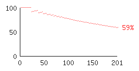 |
| H (pixels) |
|
|
This graph is a good way to compare the number of rectangles (R) produced by Filled Ellipse Algorithm 2 against a simple scan-line algorithm (such as Filled Ellipse Algorithm 1), since the number of scan lines is equal to the height of the shape (H). If R is less than H, we can deduce that Algorithm 2 is performing better than a scan-line algorithm. It can be seen that the ratio of rectangles to scan lines gradually falls from almost no improvement in the case of very eccentric ellipses, to about 59% in the case of circular shapes.
When the graph is continued to the right, the line continues to fall off towards zero, since we can draw almost the entire shape using a single tall rectangle, and just fill the top and bottom edges using a few extra rectangles. We have not shown this part of the graph because it would be possible to make a smarter scan-line algorithm which detects if the ellipse is taller than it is wide, and in that case, draw scan lines from top to bottom, rather than left to right. As we shall shortly demonstrate, our algorithm produces the same number of rectangles whether we draw those rectangles horizontally or vertically. Accordingly, an ellipse which is taller than it is wide can be rotated ninety degrees and examined in a different graph. Therefore we just show what happens when the width is constant and the height varies until the shape becomes circular.
This shows we can draw some ellipses using Algorithm 2 with only 59% as many filled rectangles as a comparable smart scan-line algorithm, which changes scanning direction if it detects the shape is taller than it is wide. Better improvements are possible if the scan-line algorithm we are comparing against always scans from top to bottom; in that case the ratio continues to asymptotically approach zero.
Examination of many such graphs, using an interactive plotting program for ellipses having widths between one pixel and 800 pixels, reveals the overall shape of most of these graphs is similar to that illustrated in Figure 7, except the graphs for smaller ellipses are less smooth, looking like the top left corner of the graph above. Figure 8 shows the graph for an ellipse of width twenty-five pixels, as the height varies.
| Width = 25 | |
| R/H (%) | 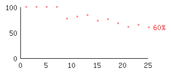 |
| H (pixels) |
|
|
The shape of the graph is fairly similar for other widths, and a value of 65% is achieved by all near-circular shapes above the width of 16 pixels, and 60% or better by near-circular shapes above 50 pixels in width.
Practical use of this algorithm within [GraphApp] has shown that drawing even quite large ellipses is not noticeably slower than other techniques, using modern hardware. Filled rectangle operations are, after all, very efficiently implemented in graphics servers. Some hardware directly supports the filling of rectangles. A lot of modern graphics hardware implements fast filling of triangles [Evans et al 1996]. On such hardware, a filled rectangle operation can be efficiently performed by drawing two triangles which fit together.
Algorithm 2 succeeds where there are many small ellipses, which may be drawn with as few as three or five rectangles, requiring only a few more drawing requests than would be the case if using a server-side filled ellipse operation. It also performs well when the filled rectangle operation implements client-side clipping, so that obscured portions of ellipses are not drawn, because this offsets the cost of drawing ellipses using filled rectangles.
Algorithm 2 has a limitation: it can only draw ellipses having odd widths and heights, since the width is 2a+1 pixels, and the height is 2b+1. We have generalised McIlroy's algorithm to handle ellipses having even widths and heights [Patrick], and found that a similar graph applies in that case.
| Width = 200 | |
| R/H (%) |  |
| H (pixels) |
|
|
The graph reveals interesting ratios of R to H particularly in the top left area. We attribute these ratios to the fact that small ellipses with even heights will always have two rectangles meeting at the middle of the shape (due to symmetry), and hence we can merge those two rectangles into one. This means shapes with an even height may use one fewer rectangle than those ellipses one pixel taller or shorter. For small height values, this can have a large apparent impact on the ratio, although the actual number of rectangles may only differ by a small number.
The method used to generate Filled Ellipse Algorithm 2 could work with other shapes, and indeed with any technique of finding the boundary points of an ellipse. Our algorithm reduces the number of rectangles by accumulating scan lines, and it is likely the same approach will produce similar improvements over existing scan-line approaches for other shapes.
 |
 |
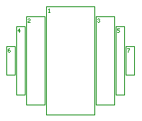 |
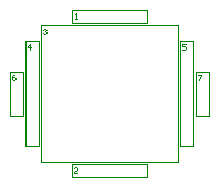
These patterns of rectangles seem quite different to the pattern shown in Figure 4, yet they share the same outline, and thus they all share the same minimal number of rectangles, by Theorem 1.
Figure 12 shows the same ellipse as Figure 4, except the rectangles are at right angles, so this is the pattern generated by exchanging x with y, and width with height, within the algorithm that produced Figure 4.
It may not be obvious that these patterns all contain the minimal number of rectangles, as produced by Filled Ellipse Algorithm 2. We shall now give an inductive proof of this fact, based on the observation that Figures 4, 10, 11 and 12 form a continuum, from a pattern of rectangles which are vertically stacked, to a pattern of rectangles which are horizontally stacked.
An important property of approximate ellipses can be seen by examining the placement of outward corners for one quadrant of the shape. As x increases across the shape, the y co-ordinates of each outward corner either strictly increase, or strictly decrease. We shall call this property diagonalism, since for any given quadrant, the lines connecting one outward corner point to the next will have a similar diagonal slope to all other such lines in that quadrant.
Definition 8: Diagonalism is a property of an axis-aligned shape if, in any given quadrant, as x increases across the quadrant, the y co-ordinates of each outward corner either strictly increase, or strictly decrease.
This property is important because it means that if we first draw a wide rectangle stretching across the shape, subsequent rectangles are stacked above or below the first, and their widths will be smaller. Likewise, if we start by drawing a tall rectangle in the middle of the shape, subsequent rectangles are shorter, and are stacked to the left and right. The relationship of height and width of these rectangles is what gives us an approximate ellipse, but the same property is true of other shapes, such as that shown in Figure 13.
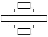
This shape is similar to the ellipse because the lines connecting adjacent outward corner points in each quadrant exhibit diagonalism, and the slopes of those lines have the same sign as in an ellipse. If the slopes were reversed, we would have a saddle-shape for which the following proof would not apply.
The proof of Theorem 2 relies on the observation that the patterns of non-overlapping rectangles can be rearranged without changing their number. Theorem 2 concerns itself only with approximate ellipses, but it will also work for a family of shapes which have diagonalism, are axis-aligned, and for which the slopes of lines joining outward corners in each quadrant have the same sign as they would in an ellipse.
Proof of Theorem 2
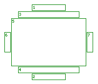
Assume we have a method to generate the pattern of non-overlapping rectangles to fill an approximate ellipse, as shown in Figure 4. We wish to move to the next pattern in the sequence, in this case Figure 10. At each step, three rectangles are redrawn as a different set of three rectangles, which cover the same area, as shown in Figure 14.
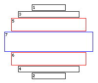
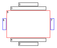
The rectangles numbered 5 and 6 in the shape on the left become the rectangle numbered 5 on the right. In the process, the rectangle numbered 7 is split, producing two new rectangles numbered 6 and 7 in the shape on the right. The new rectangle touches four outward corners, but splits a rectangle which formerly touched four outward corners, creating two new rectangles which each touch only two outward corners.
Figure 15 shows the next step in the process.
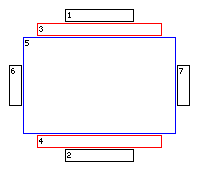
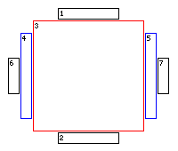
Once again, it can be seen that three rectangles are rearranged into a different set of three rectangles, and so the number of rectangles stays constant. Here, rectangles 3 and 4 are joined to form rectangle 3, while rectangle 5 is split to form rectangles 4 and 5.
This process works because in a given quadrant of the approximate ellipse, there is a relationship between the x and y co-ordinates of outward corner points. As x increases, y increases or decreases depending on which quadrant we are discussing. Thus, when generating this continuum of patterns, we can be sure that three rectangles can be redrawn in the manner described because they form a 'plus sign' shape, as illustrated in Figure 16.

Note that the figure is not meant to imply the lengths of each straight line in the plus sign are the same; rather we are illustrating that any axis-aligned arrangement of two rectangles which cross each other can be drawn using three non-overlapping rectangles. It can also be seen that three is the smallest number of non-overlapping rectangles which can fill this plus sign shape.
The important point to note about the plus sign shape is that the approximate ellipses we've been discussing are generated by repeated use of this shape. The first horizontal bar of the plus sign is a rectangle which stretches across the entire ellipse. The vertical bar of the plus sign is formed from rectangles of a slightly smaller width, stacked above and below the horizontal bar. Once these are drawn, those vertical bars can be seen as the horizontal bar of a new plus sign shape, with the new vertical bar forming two more rectangles of slightly smaller width, stacked around it. This process repeats to form the ellipse.
It does not matter which four corner points we use to define the 'first' horizontal bar. If we start with a large central rectangle, we can think of it as a horizontal bar of a plus sign, so we can repeatedly apply the plus sign shape to produce rectangles stacked above and below it. We can also think of that first large rectangle as a vertical bar in the plus shape, and move outwards generating horizontal bars. This produces the patterns seen in Figures 10 and 11.
This 'plus sign' method of generating an ellipse always produces diagonalism, because the outward corners are diagonally displaced from each other. Lines connecting the outward corner points will have the same sign slope in each quadrant as axis-aligned ellipses. A shape such as that in Figure 13 can therefore also be generated using the 'plus sign' pattern.
The patterns shown in Figures 4, 10, 11 and 12 are part of a continuum. We can start with Figure 4, and transform it to generate Figure 10, by swapping two of the 'bars' of a plus sign within the pattern. Because the total number of rectangles remains constant at each step in the transformation, from using only wide rectangles to using only tall rectangles, by induction we can be certain that all filled approximate ellipses having the same perimeter which are drawn within this continuum of patterns will share the same number of rectangles.
In particular, it does not matter whether the shape is scanned horizontally (as in Figure 4) or vertically (as in Figure 12), the number of rectangles will be the same. Therefore, an algorithm which always scans in one direction, such as top to bottom, is no worse than an algorithm which produces any of the other patterns.
In fact, producing these other patterns, particularly the intermediate ones such as those shown in Figures 10 and 11, would seem to require more computation in the program, because we must calculate the position of a central rectangle, and fill outwards in each of the four directions surrounding that rectangle, instead of just travelling in one direction. So even though the number of rectangles, and the message traffic produced by filled rectangle requests, is the same for all of these shapes, the computation in the program is probably slightly greater for the patterns in Figures 10 and 11, than for those shown in Figures 4 or 12.
We can conclude that an algorithm which always draws an approximate filled ellipse using the pattern shown in Figure 4 (such as Filled Ellipse Algorithm 2) is no worse than any of the other patterns shown in Figures 10 to 12, and may actually be simpler to generate than many of those others. This assumes we are counting the cost of filled rectangle messages and the cost of client-side computation, and that we wish to avoid drawing over any pixels more than once.

The central portion of the shape will be drawn N times, where N is the total number of rectangles drawn, since this portion of the shape is the intersection of all the rectangles. The areas horizontally and vertically adjacent to that central area will be drawn N-1 times, and so on outwards. This is a problem if using a drawing mode which requires that each pixel be changed exactly once, or changed an odd number of times (such as exclusive-or mode), because clearly this algorithm satisfies neither of those requirements in the general case.
Additionally, this algorithm wastes time at the graphics server, because even though the number of filled rectangle requests is roughly halved (by combining rectangles on opposite sides of a symmetric shape into a single rectangle), drawing the pixels many times may actually be slower than the time saved by reducing the message traffic. The central area of the shape is drawn N times, and N is proportional to the number of outward corners, so drawing a large ellipse with many corners could change the central pixels many times. This may be slower than the previous algorithm discussed, or it may be faster, depending on the relative speeds of sending messages to the graphics server, and implementing those instructions at the server. Graphics hardware is increasing in speed all the time, so perhaps this algorithm has a use in some circumstances.
Theorem 3: The minimum number of overlapping rectangles which can be used to fill an axis-aligned shape which has N outward corners, is N/4.
Proof of Theorem 3
A vertically and horizontally symmetrical shape must have a number of outward corners which is a multiple of four, since symmetry implies if there is one outward corner in a given quadrant, there is another outward corner in each of the other three quadrants. These reflected corners will share either the same x or y co-ordinate as the corresponding corners in each adjacent quadrant.
Thus, if there are N outward corners in the shape, there must be N/4 outward corners in one quadrant. This will be a whole number.
Additionally, because the corners share co-ordinates through reflection, a single corner when mirrored forms four points which can be joined by one rectangle. This is due to the fact that reflection about a horizontal or vertical axis preserves either the x or y co-ordinate of a point, and thus we can draw a line connecting two points which are reflections of each other, and the set of four lines produced in this way will form a rectangle. The set of rectangles shown in Figure 17 illustrate this point clearly.
The only way to generate an outward corner in a shape is to fill some pixels inside that shape, using a rectangle of non-zero area. Thus, to generate four outward corners in a figure, which are produced by reflection about vertical and horizontal axes of symmetry, one rectangle suffices. This is true of axis-aligned ellipses because they can be generated by the plus sign shape mentioned earlier. More general shapes which cannot be drawn by a set of rectangles related by the plus sign, might require more rectangles, but for ellipses, four corner points can be generated by one filled rectangle.
Thus, if there are N corners in a horizontally and vertically symmetrical shape, the minimum number of rectangles which can be used to fill that shape is N/4, one for each outward corner in a single quadrant. In ellipses, we can always use this minimal number, as illustrated in Figure 17. In that example, there are sixteen outward corners, giving the correct number of four rectangles needed to fill the shape.
This shows Filled Ellipse Algorithm 3 is optimal in the number of overlapping rectangles used to fill axis-aligned approximate ellipses.
Algorithm 2 uses about twice as many rectangles as Algorithm 3, to avoid overlaps. If the cost to request a filled rectangle was very high compared with the cost to actually fill the rectangle within the graphics system, Algorithm 3 may have some application because of the halving of the number of requests.
Anything which is generated in the 'plus sign' shape should follow the same rules as given here for ellipses. The hyperbolic shape shown in Figure 13 should also share the same minimal number of rectangles, because there is nothing in the proof of Theorem 1 which depends on the outward corners touching an approximate ellipse.
Shapes which are not symmetrical should contain a minimal number of rectangles described by similar formulas.
One quadrant of an axis-aligned ellipse, for instance, while not being symmetrical, might have a similar formula to count the number of rectangles. Each rectangle would be truncated at the axes of symmetry which run through the central point of the ellipse. One rectangle will be able to touch three outward corner points, one could touch two, and the remaining rectangles would only be able to touch one outward corner each, so the formula should be 2 + N - 5, which is N - 3, given that there are N outward corners, for N > 4. No attempt is made to prove this here, but an example pattern is shown in Figure 18.

We have implemented filled rectangle algorithms for line slices [Bresenham 1985-2] and pie shapes. Again, no proof is given that these patterns would produce a minimal number of rectangles. Bresenham lines do not follow the rule that a rectangle can only touch four or two or one outward corners; it is possible to have rectangles which touch three outward corners, as shown in Figure 19. Proving that an algorithm produces a minimal number of rectangles in this case is a matter for further work.

For other shapes, there may be some incentive to use an algorithm similar to Algorithm 2. If we were drawing the outline of an ellipse instead of filling it, we can achieve some reduction in the number of drawing requests, as shown in Figure 20.

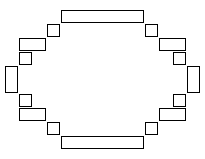
A simple technique can be used to automatically generate Algorithm 2 and others like it: use a scan line algorithm which draws the shape one line at a time by scanning downwards, but cache filled rectangle requests and merge them with subsequent requests to draw adjacent rectangles having the same width or height.
For instance, Xlib (the low-level graphics request handling library within X-Windows) does not immediately pass on requests to fill a rectangle to the graphics system. Instead, it remembers that request, and if the next drawing request is for a filled rectangle adjacent to the previous rectangle, it combines the two requests into a single request, if possible. This technique would produce similar results to our Algorithm 2, providing the lines were scanned strictly from top to bottom, since Xlib only remembers one rectangle.
Of course, the cost of doing this is that an algorithm cannot as easily exploit symmetry to draw scan lines using reflection, or it may lose the advantages conferred by caching. Algorithm 2, presented in this paper, achieves efficiency by using symmetry (thus reducing computation) and using a minimal number of rectangles.
Nevertheless, it is likely that such a simple expedient as caching and combining rectangles will produce optimal or near-optimal solutions to similar problems without the need to develop special-purpose algorithms for each shape. Increasing the number of rectangles remembered within Xlib, for instance, would allow symmetrically generated shapes to use fewer filled rectangle requests, at the expense of more comparisons needed to combine adjacent rectangles, since each remembered rectangle must be checked for adjacency.
Rendering objects from the real world often does not result in absolute symmetry in any case, so the computational cost saving symmetry provides is increasingly unimportant, since computing speeds are ever increasing. That being said, it is good to know that rules of thumb, such as combining adjacent rectangles mathematically before sending them to a rendering engine, is a technique with a sound mathematical basis.
One use of this algorithm is in providing a portable graphics programming package, where each shape is drawn using filled rectangles. This will work on a variety of graphics platforms, since filled rectangles are likely to be implemented correctly everywhere, whereas filled ellipses are demonstrably not as trustworthy.
Further work could concentrate on designing and assessing similar algorithms for other common graphics primitives, such as outlines of ellipses and elliptical arcs, lines, filled elliptical arc wedges and polygons.
[Bresenham 1977] J. E. Bresenham "A linear algorithm for incremental display of digital arcs," Commun. ACM. 20(2) (Feb. 1977): 100-106.
[Bresenham 1985-1] J. E. Bresenham "Algorithms for circular arc generation," Fundamental Algorithms for Computer Graphics, R.A. Earnshaw, ed., NATO ASI Series, Vol. F17, Springer Verlag, Berlin, (1985): 197-218.
[Bresenham 1985-2] J. E. Bresenham "Run length slice algorithm for incremental lines," Fundamental Algorithms for Computer Graphics, R.A. Earnshaw, ed., NATO ASI Series, Vol. F17, Springer Verlag, Berlin, (1985): 59-104.
[Evans et al 1996] F. Evans, S. S. Skiena, and A. Varshney "Optimizing Triangle Strips for Fast Rendering," IEEE Visualization '96, (Oct. 1996): 319-326.
[Freeman 1974] H. Freeman "Computer Processing of Line-Drawing Images," Computing Surveys 6 (1974): 63.
[GraphApp] Web reference: http://www.cs.usyd.edu.au/~loki/graphapp/ Visited 2001.
[Horn 1976] B. K. P. Horn "Circle generators for display devices," Comput. Graph. Image Process. 5 (1976): 280-288
[Kappel 1985] M. R. Kappel "An ellipse-drawing algorithm for raster displays," Fundamental Algorithms for Computer Graphics, R.A. Earnshaw, ed., NATO ASI Series, Vol. F17, Springer Verlag, Berlin, (1985): 257-280.
[McIlroy 1983] M. D. McIlroy "Best approximate circles on integer grids," ACM Trans. Graph. 2(4) (Oct. 1983): 237-263
[McIlroy 1992] M. D. McIlroy "Getting raster ellipses right," ACM Trans. Graph. 11(3) (Jul. 1992): 259-275
[Metzger 1969] R. A. Metzger "Computer generated graphics segments in a raster display," Spring 1969 Joint Computer Journal Conference, AFIPS Conf. Proc.: 161-172
[Patrick] L. Patrick "GraphApp: A Portable Graphics Package Designed for Teaching," Ph.D. Thesis School of Information Technology, University of Sydney 2002 (to appear)
[Petzold 1992] C. Petzold "Programming Window 3.1," Microsoft Press, 3rd ed. 1992
[Pike 1991] R. Pike "8 1/2, the Plan 9 Window System," Proc. Summer 1991 USENIX Conf. Nashville (Jun. 1991)
[Pitteway 1967] M. L. V. Pitteway "Algorithm for drawing ellipses or hyperbolae with a digital plotter," Computer J. 10 (1967):282-289.
[Scheifler and Gettys 1992] R. W. Scheifler and J. Gettys "X Window System," Digital Press, 3rd ed. 1992
[Van Aken 1984] J. Van Aken "An efficient ellipse-drawing algorithm," IEEE Comput. Graph. and Appl. 4(9) (Sept 1984): 24-35.
[Van Aken and Novak 1985] J. Van Aken and M. Novak "Curve drawing algorithms for raster displays," ACM Trans. Graph. 4(2) (Apr. 1985): 147-169